|
|
||
|---|---|---|
| .github | ||
| Adafruit_BBIO | ||
| docs | ||
| m4 | ||
| overlays | ||
| source | ||
| test | ||
| udev | ||
| .gitignore | ||
| .travis.yml | ||
| Adafruit_I2C.py | ||
| CHANGELOG.md | ||
| configure.ac | ||
| distribute_setup.py | ||
| fix_py_compile.py | ||
| install_all_python_versions.sh | ||
| Makefile | ||
| Makefile.am | ||
| MANIFEST.in | ||
| pytest_all_versions.sh | ||
| README.md | ||
| setup.py | ||
| tox.ini | ||
Adafruit Beaglebone I/O Python API
![]()

Adafruit BBIO is an API to enable GPIO, PWM, ADC, UART, SPI and eQEP (Quadrature Encoder) hardware access from Python applications running on the Beaglebone.
-
It is recommended to use an official BeagleBoard.org Debian image
- Currently recommended image: Debian 10.3 "Buster" IoT (2020-04-06) (default kernel is 4.19.x-ti)
-
Adafruit_BBIO supports Linux kernels 3.8 through 4.19
-
New versions of Adafruit_BBIO may break backwards compatibility. Please read the changelog.
-
It is recommended to use Python 3
Installation on Debian
Note: Follow the instructions on BeagleBoard.org to get connected to the Internet
Easiest:
sudo apt-get update
sudo apt-get install build-essential python3-dev python3-pip -y
sudo pip3 install Adafruit_BBIO
Manual:
sudo apt-get update
sudo apt-get install build-essential python3-dev python3-pip -y
git clone git://github.com/adafruit/adafruit-beaglebone-io-python.git
cd adafruit-beaglebone-io-python
sudo python3 setup.py install
Upgrade Adafruit_BBIO to latest version on PyPI:
sudo pip3 install --upgrade Adafruit_BBIO
Usage
Using the library is very similar to the excellent RPi.GPIO library used on the Raspberry Pi. Below are some examples.
Pin Numbers
Please note that there is no '0' prefix for the pin numbers. For example, pin 7 on header P8 is P8_7.
Correct:
GPIO.setup("P8_7", OUT )
INCORRECT:
GPIO.setup("P8_07", OUT )
Refer to pins_t table[] in common.c all the pin labels.
config-pin
config-pin is now used on the official BeagleBoard.org Debian Jessie and Stretch images to control pin mode (e.g. pin mux).
debian@beaglebone:~$ config-pin -q P9_14
P9_14 Mode: pwm

debian@beaglebone:~$ config-pin -l P9_14
default gpio gpio_pu gpio_pd pwm

debian@beaglebone:~$ config-pin P9_14 gpio

debian@beaglebone:~$ config-pin -q P9_14
P9_14 Mode: gpio Direction: in Value: 0

debian@beaglebone:~$ config-pin P9_14 pwm

debian@beaglebone:~$ config-pin -q P9_14
P9_14 Mode: pwm
GPIO Setup
Import the library, and setup as GPIO.OUT or GPIO.IN::
import Adafruit_BBIO.GPIO as GPIO
GPIO.setup("P8_14", GPIO.OUT)
You can also refer to the pin names::
GPIO.setup("GPIO0_26", GPIO.OUT)
GPIO Output
Setup the pin for output, and write GPIO.HIGH or GPIO.LOW. Or you can use 1 or 0.::
import Adafruit_BBIO.GPIO as GPIO
GPIO.setup("P8_14", GPIO.OUT)
GPIO.output("P8_14", GPIO.HIGH)
On-Board LEDs
On-board LEDs (USR0-USR3) are handled by LED class driver rather than the GPIO pin driver.
They have a different path in the /sys/ filesystem.
Setup the pin for output and write GPIO.HIGH or GPIO.LOW::
import Adafruit_BBIO.GPIO as GPIO
import time

for i in range(4):
    GPIO.setup("USR%d" % i, GPIO.OUT)

while True:
    for i in range(4):
        GPIO.output("USR%d" % i, GPIO.HIGH)
        time.sleep(1)
    for i in range(4):
        GPIO.output("USR%d" % i, GPIO.LOW)
        time.sleep(1)
GPIO Input
Inputs work similarly to outputs.:
import Adafruit_BBIO.GPIO as GPIO
GPIO.setup("P8_14", GPIO.IN)
Polling inputs:
if GPIO.input("P8_14"):
  print("HIGH")
else:
  print("LOW")
Waiting for an edge (GPIO.RISING, GPIO.FALLING, or GPIO.BOTH:
GPIO.wait_for_edge(channel, GPIO.RISING)

or

GPIO.wait_for_edge(channel, GPIO.RISING, timeout)
Detecting events:
GPIO.add_event_detect("P9_12", GPIO.FALLING)
#your amazing code here
#detect wherever:
if GPIO.event_detected("P9_12"):
  print("event detected!")
PWM
The PWM Duty Cycle range was reversed in 0.0.15 from 100(off)-0(on) to 0(off)-100(on). Please update your code accordingly.
import Adafruit_BBIO.PWM as PWM
#PWM.start(channel, duty, freq=2000, polarity=0)
#duty values are valid 0 (off) to 100 (on)
PWM.start("P9_14", 50)
PWM.set_duty_cycle("P9_14", 25.5)
PWM.set_frequency("P9_14", 10)

PWM.stop("P9_14")
PWM.cleanup()

#set polarity to 1 on start:
PWM.start("P9_14", 50, 2000, 1)
ADC
import Adafruit_BBIO.ADC as ADC
ADC.setup()

#read returns values 0-1.0
value = ADC.read("P9_40")

#read_raw returns non-normalized value
value = ADC.read_raw("P9_40")
UART
config-pin P9.21 uart  # UART2_TXD
config-pin P9.22 uart  # UART2_RXD
config-pin P9.24 uart  # UART1_TXD
config-pin P9.26 uart  # UART1_RXD
sudo pip install pyserial
import Adafruit_BBIO.UART as UART
import serial

UART.setup("UART1")

with serial.Serial(port = "/dev/ttyO1", baudrate=9600) as ser:
    print("Serial is open!")
    ser.write(b"Hello World!")
- Available UART names on BeagleBone
UART1: /dev/ttyO1, Rx: P9_26, Tx: P9_24UART2: /dev/ttyO2, Rx: P9_22, Tx: P9_21UART4: /dev/ttyO4, Rx: P9_11, Tx: P9_13UART5: /dev/ttyO5, Rx: P8_38, Tx: P8_37- note:
UART5requiresdisable_uboot_overlay_video=1in/boot/uEnv.txt
- Available UART names on PocketBeagle
PB-UART0: /dev/ttyO0, Rx: P1_30, Tx: P1_32PB-UART1: /dev/ttyO1, Rx: P2_11, Tx: P2_09PB-UART2: /dev/ttyO2, Rx: P1_08, Tx: P1_10
- Loopback test with UART1 and UART2
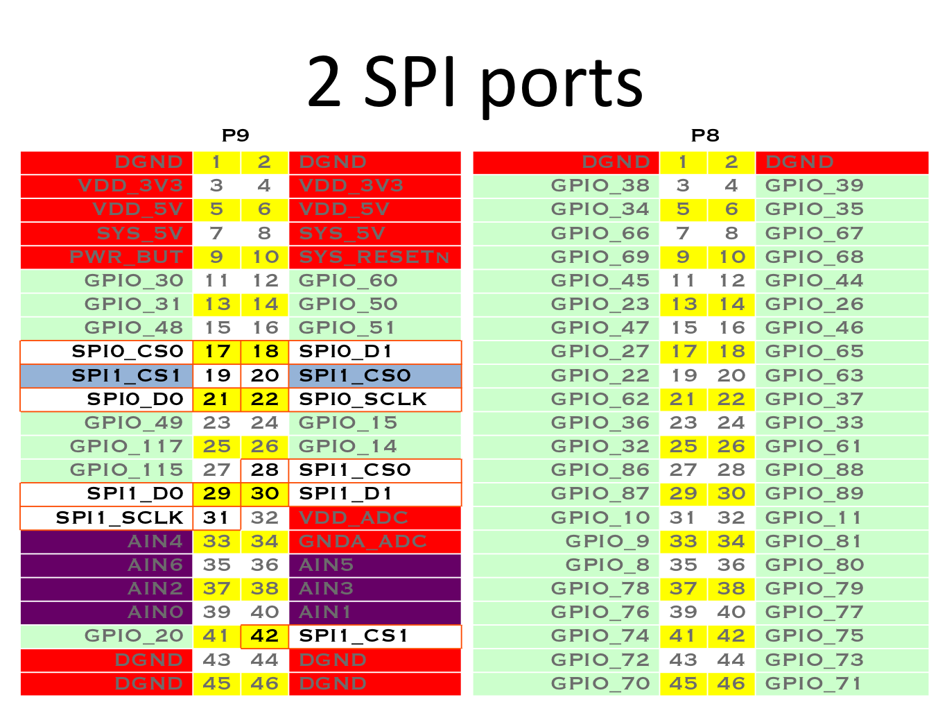
SPI
- Use
config-pinto set pin mode for SPI pins- SPI0
- SPI0_CS0:
config-pin p9.17 spi_cs - SPI0_D0:
config-pin p9.21 spi - SPI0_D1:
config-pin p9.18 spi - SPI0_SCLK:
config-pin p9.22 spi_sclk
- SPI0_CS0:
- SPI1
- SPI1_CS0:
config-pin p9.20 spi_cs - SPI1_CS0:
config-pin p9.28 spi_cs - SPI1_CS1:
config-pin p9.19 spi_cs - SPI1_CS1:
config-pin p9.42 spi_cs - SPI1_D0:
config-pin p9.29 spi - SPI1_D1:
config-pin p9.30 spi - SPI1_SCLK:
config-pin p9.31 spi_sclk
- SPI1_CS0:
- SPI0
- Example:
from Adafruit_BBIO.SPI import SPI
#spi = SPI(bus, device) #/dev/spidev<bus>.<device>

# /dev/spidev0.0
spi = SPI(1,0)
print(spi.xfer2([32, 11, 110, 22, 220]))
spi.close()

# /dev/spidev0.1
spi = SPI(1,1)
print(spi.xfer2([32, 11, 110, 22, 220]))
spi.close()

# /dev/spidev1.0
spi = SPI(2,0)
print(spi.xfer2([32, 11, 110, 22, 220]))
spi.close()

# /dev/spidev1.1
spi = SPI(2,1)
print(spi.xfer2([32, 11, 110, 22, 220]))
spi.close()
eQEP
To use the enhanced Quadrature Encoder Pulse (eQEP) module, please refer to the Encoder module's documentation.
Running tests
Install py.test to run the tests. You'll also need the python compiler package for pytest:
sudo pip3 install pytest
Execute the following in the root of the project:
pytest
NOTE: sudo should not be required as udev configures group ownership and permission for GPIO and PWM
Reporting issues
When reporting issues, plesae run the following script which will print the system configuration:
sudo /opt/scripts/tools/version.sh
and paste the output in a reply.
This script should be present for any Debian or Ubunut image downloaded from: https://beagleboard.org/ or https://rcn-ee.com/
Credits
The BeagleBone IO Python library was originally forked from the excellent MIT Licensed RPi.GPIO library written by Ben Croston.
License
Written by Justin Cooper, Adafruit Industries. BeagleBone IO Python library is released under the MIT License.