| assets | ||
| Adafruit 555 PWM Output STEMMA.brd | ||
| Adafruit 555 PWM Output STEMMA.sch | ||
| license.txt | ||
| README.md | ||
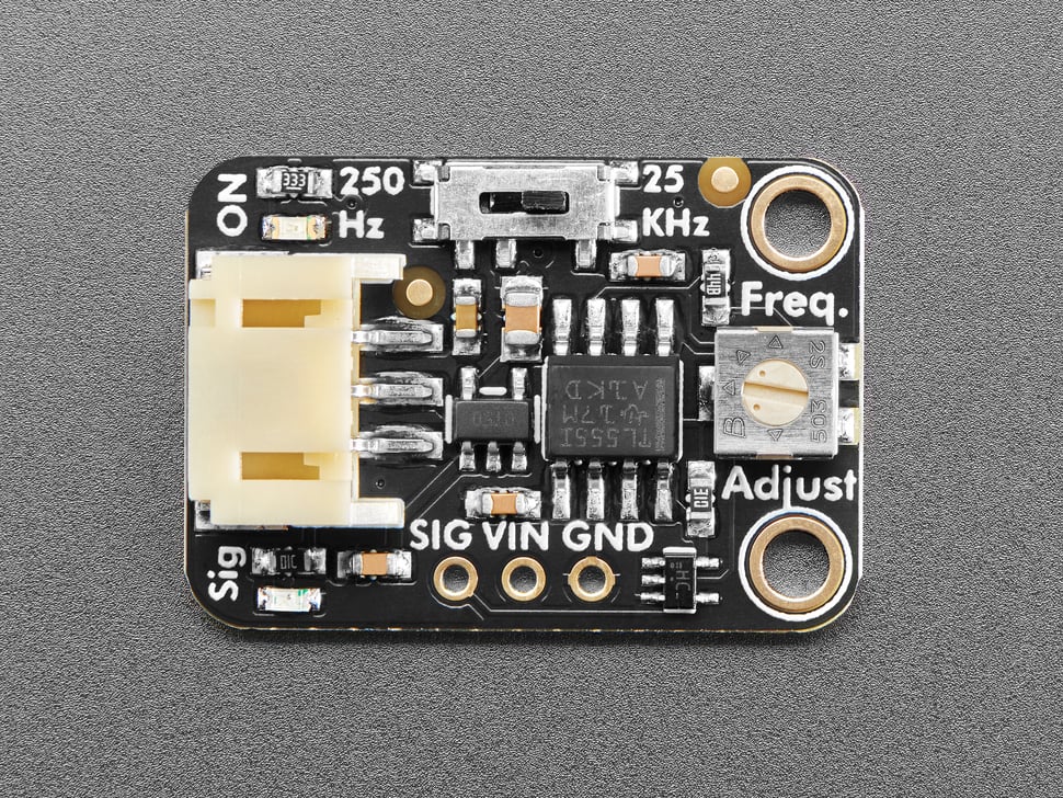
Adafruit 555 PWM Output STEMMA - 1.4K to 25 KHz or 1.4 to 250 Hz - STEMMA JST PH 2mm PCB
Click here to purchase one from the Adafruit shop
PCB files for the Adafruit 555 PWM Output STEMMA - 1.4K25 KHz or 1.4250 Hz - STEMMA JST PH 2mm.
Format is EagleCAD schematic and board layout
Description
How many times have we heard "hey you could have just replaced that microcontroller with a 555"? Maybe 555 times! But we always find wiring up a timer chip to be a bit of a pain, you need quite a few components - especially if you want a buffered output. That's why we designed the Adafruit 555 PWM Output STEMMA - a fully-assembled 555 timer board with adjustable PWM square-wave output.
We originally came up with this idea when someone requested we make a 'PC Fan Dummy' board, that can generate a 100Hz signal for faking a PC fan's tachometer signal to a motherboard. But then we thought that sometimes we want a square wave for driving a piezo, or as an audio input, or to modulate an IR signal. So we made it a little more general-purpose.
You can select between two 'ranges': approximately 1.4K25 KHz or 1.4250 Hz. The onboard trimmer pot will tune the actual output between those values. You can use a logic analyzer, oscilloscope, multimeter with frequency-counting, or even an audio input jack on a computer, to determine the precise value if you need more than a rough number. The output is a DC square wave, driven by a 74HC1G04
buffer so it can sink/source up to 12.5mA.
You can power the board from 3V to 12VDC, an onboard regulator will pin the input to the 555 and buffer to 5V max. That means that between 3V and 5V power, the signal peak will be at the same logic level as the power. Above 5V, the output will be pegged to 5V.
Each STEMMA board is a fully assembled and tested PCB but no cable. No soldering is required to use it, but you will need to pick up a 2mm pitch, 3-pin STEMMA JST PH cable. Alternatively, if you do want to solder, there's a 0.1" spaced header for power/ground/signal.
License
Adafruit invests time and resources providing this open source design, please support Adafruit and open-source hardware by purchasing products from Adafruit!
Designed by Limor Fried/Ladyada for Adafruit Industries.
Creative Commons Attribution/Share-Alike, all text above must be included in any redistribution. See license.txt for additional details.